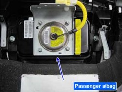
| COMPONENT LOCATION |

| GENERAL DESCRIPTION |
Passenger Air bag module (hereinafter referred to PAB) located at passenger side crush pad protects passenger by reducing impact of collision.
PAB is consist of air bag, pat cover and inflator.
Air bag reduces impact of collision by fillied up gas.
Inflator keeps gas and uses it to deploy air bag on collision.
Never measure resistance of PAB directly, Current of measuring device may cause unexpected air bag deploy. |
| DTC DESCRIPTION |
The SRSCM sets DTC B1352 if the measured resistance value of PAB circuit is more than the threshold value.
*In this case, SRSCM checks if there’s any fault in circuit by sending current for a while
| DTC DETECTING CONDITION |
| Item | Detecting Condition | Possible cause | |||||||||||
| DTC Strategy |
|
| |||||||||||
| Enable Conditions |
| ||||||||||||
| Threshold Value |
| ||||||||||||
| Diagnostic Time | Qualification |
| |||||||||||
| De-Qualification |
| ||||||||||||
| SPECIFICATION |
| Test Condition | Resistance |
| Ignition ON | 1.6Ω ≤ Squib resistance ≤ 6.0Ω |
| DIAGNOSTIC CIRCUIT DIAGRAM |

| MONITOR SCANTOOL DATA |
| 1. | Ignition “OFF”, connect scantool. |
| 2. | Ignition “ON”& Engine “OFF”, select “Current Data” mode. |
| 3. | Monitor the “Passenger airbag resistance” parameter on the Scantool.
Fig.1) Normal Data |
| 4. | Is parameter displayed within specifications?
|
| TERMINAL AND CONNECTOR INSPECTION |
| 1. | Many malfunctions in the electrical system are caused by poor harness and terminals. Faults can also be caused by interference from other electrical systems, and mechanical or chemical damage. |
| 2. | Thoroughly check shorting bar/shorting bar release pin and connectors for looseness, poor connection, bending, corrosion, contamination, deterioration, or damage. |
| 3. | Has a problem been found?
|
| SQUIB CIRCUIT INSPECTION |
| 1. | Ignition “OFF”. |
| 2. | Disconnect (-) terminal cable from battery and wait for 1 minutes or more. |
| 3. | Remove the PAB module and connect the dummy and dummy adapter to PAB harness connector.
|
| 4. | Connect (-) terminal cable to battery and Ignition “ON” & Engine “OFF” and wait for 30 seconds or more. |
| 5. | Connect scantool to Data Link Connector(DLC) and clear DTC with scantool and diagnose again.
|
| 6. | Is DTC present problem ?
|
| MAIN HARNESS CIRCUIT INSPECTION |
| 1. | Ignition “OFF”. |
| 2. | Disconnect the battery (-) terminal cable from the battery and wait at least one minutes. |
| 3. | Disconnect PAB connector and SRSCM main harness connector.
|
| 4. | Measure resistance between terminal “Low.1” and “High.1” of the PAB harness connector.
|
| 5. | Is the measured resistance within specifications?
|


