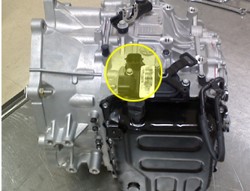
| COMPONENT LOCATION |

| GENERAL DESCRIPTION |
The PCM/TCM receives signals from the Inhibitor Switch based on the selected gear from driver input. When the vehicle is moving and the gear selected, the PCM/TCM controls the gear ratio for optimized transmission shift control.
| DTC DESCRIPTION |
When an undefined code is sent from the Inhibitor Switch to the PCM/TCM without specific transmission pattern, the PCM/TCM sets DTC P0705.
| DTC DETECTING CONDITION |
| Item | Detecting Condition | Possible Cause | ||||||||
| DTC Strategy |
|
| ||||||||
| Enable Conditions |
| |||||||||
| Threshold value |
| |||||||||
| Detecting Time |
| |||||||||
| Fail safe |
|
| SPECIFICATION |
| P | P-R | R | R-N | N | N-D | D | D-X | X | X-Y | Y | Y-Z | Z | |
| S1 | 1 | 0 | 0 | 0 | 1 | 1 | 1 | 1 | 1 | 1 | 0 | 0 | 0 |
| S2 | 0 | 0 | 0 | 1 | 1 | 0 | 0 | 1 | 1 | 0 | 0 | 1 | 1 |
| S3 | 1 | 1 | 0 | 0 | 0 | 0 | 0 | 0 | 1 | 1 | 1 | 1 | 1 |
| S4 | 1 | 1 | 1 | 1 | 1 | 1 | 0 | 0 | 0 | 0 | 0 | 0 | 1 |
| DIAGNOSTIC CIRCUIT DIAGRAM |

| SIGNAL WAVEFORM & DATA |

| MONITOR GDS DATA |
| 1. | Connect scanner to Data Link Connector(DLC). |
| 2. | Ignition “ON” & engine “OFF”. |
| 3. | Selet “Currnet Data”mode and monitor “Inhibitor switch” parameter. |
| 4. | Change a shift lever from P-range to D-range.
Fig 1) P range Fig 2) R range Fig 3) N range Fig 4) D range |
| 5. | Is the Inhibitor switch value changed in specification?
|
| TERMINAL & CONNECTOR INSPECTION |
| 1. | Many malfunctions in the electrical system are caused by poor harness and terminals. Faults can also be caused by interference from other electrical systems, and mechanical or chemical damage. |
| 2. | Thoroughly check connectors for looseness, poor connection, bending, corrosion, contamination, deterioration, or damage. |
| 3. | Has a problem been found?
|
| POWER CIRCUIT INSPECTION |
| 1. | Disconnect an Inhibitor switch. |
| 2. | IG KEY “ON”” & Engine “OFF”. |
| 3. | Measure voltage between supplied power and ground at inhibitor circuit.
|
| 4. | Is the measured voltage within specifications?
|
| SIGNAL CIRCUIT INSPECTION |
| 1. | Connect an Inhibitor switch. |
| 2. | Ignition “ON” & Engine “OFF”. |
| 3. | Measure voltages between each terminal and chassis ground during shift lever changed “P, R, N, D”.
| |||||||||||||||||||||||||||||||||||||||||||||||
| 4. | Is the measured voltage within specifications?
|


