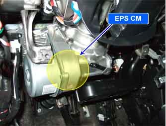
| COMPONENT LOCATION |

| GENERAL DESCRIPTION |
EPS CM controls EPS solenoid current accurately according to vehicle speed. EPS CM monitors that operating voltage supplied as IG S/W is too high or too low on “power supply terminal”. If excessive high voltage or low voltage is detected, EPS CM stops current supply to solenoid to prevent unexpected operation or damage.
| DTC DESCRIPTION |
EPS CM sets this code if high voltage caused by faulty alternator or poor connention in power supply circuit is detected.
| DTC DETECTING CONDITION |
| Item | Detecting Condition | Possible cause | ||||||||
| DTC Strategy |
|
| ||||||||
| Enable conditions |
| |||||||||
| Threshold value |
| |||||||||
| Fail Safe |
| |||||||||
| Restoration conditions |
|
| SPECIFICATION |
| Bat. Voltage | IG Key ON | ENG. ON |
| Approx. 11.8 [V]~12.5 [V] | Approx. 12.5 [V] ~ 14.5 [V] |
| DIAGNOSTIC CIRCUIT DIAGRAM |

| MONITOR SCANTOOL DATA |
| 1. | Connect scantool to Data Link Connector(DLC). |
| 2. | Start engine and turn the headlight on. |
| 3. | Monitor the “BATTERY VOLTAGE” parameter on the scantool. |
| 4. | Maintaining ENG. RPM at 2,500RPM(idle) over 2 minutes.
|
| 5. | Is parameter within specifications?
|
| TERMINAL AND CONNECTOR INSPECTION |
| 1. | Many malfunctions in the electrical system are caused by poor harness and terminals. Faults can also be caused by interference from other electrical systems, and mechanical or chemical damage. |
| 2. | Thoroughly check all connectors (and connections) for looseness, bending, corrosion, contamination, deterioration, and/or damage. |
| 3. | Has a problem been found?
|
| CHARGING SYSTEM INSPECTION |
| 1. | Engine “ON” |
| 2. | headlight”ON”. |
| 3. | Measure voltage between terminal (+) and (-) of battery while maintaining ENG RPM 2,500RPM over 2 minutes.
|
| 4. | Is the measured voltage within specifications?
|
| POWER CIRCUIT INSPECTION |
| ■ Open or Short Check |
| 1. | Ignition “OFF” |
| 2. | Disconnect EPS CM connector. |
| 3. | Engine “ON”, headlight “ON”. |
| 4. | Measure voltage between battery power terminal of EPS CM harness connector and chassis ground maintaining ENG. RPM at 2,500RPM(idle) over 2 minutes.
|
| 5. | Is the measured voltage within specifications?
|
| GROUND CIRCUIT INSPECTION |
| ■ Open or Short Check |
| 1. | Ignition “OFF”. |
| 2. | Disconnect EPS CM connector. |
| 3. | Measure resistance between ground terminal of EPS CM harness connector and chassis ground.
|
| 4. | Is the measured resistance within specifications?
|


