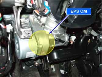
| COMPONENT LOCATION |

| GENERAL DESCRIPTION |
EPS is designed to provide directional control and smooth feeling to driver when driver operates steering wheel. There is a function to detect rotation speed and direction of steering wheel in Torque Sensor. Rotation speed and direction signals are used for “damper” and “return” control, “assist” control.
| DTC DESCRIPTION |
Steering angle sensor error can be set when loss of steering angle due to internal fault or open in ECU internal circuit occurs. If steering sensor error occurs EPS CM stops “damper” and “return” control. Therefore driver can be uncomfortable due to no return force during U-Turn, high speed driving, but there is no problem for driving because basic assist control still alives.
| DTC DETECTING CONDITION |
| Item | Detecting Condition | Possible cause | ||||||||
| DTC Strategy |
|
| ||||||||
| Enable conditions |
| |||||||||
| Threshold value |
| |||||||||
| Fail Safe |
| |||||||||
| Restoration conditions |
|
| MONITOR SCANTOOL DATA |
| 1. | Connect scantool to Data Link Connector(DLC) |
| 2. | Ignition “ON” & Engine “ON”. |
| 3. | Turn the steering wheel to the left or right. |
| 4. | Monitor the “STEERING ANGLE SNSR” parameters on the Scantool.
|
| 5. | Whenever steering wheel is turned, is the steering sensor′s scantool data changed?
▶ Go to “W/Harness Inspection” procedure. |
| 6. | Perform steering angle sensor calibration.
|
| TERMINAL AND CONNECTOR INSPECTION |
| 1. | Many malfunctions in the electrical system are caused by poor harness and terminals. Faults can also be caused by interference from other electrical systems, and mechanical or chemical damage. |
| 2. | Thoroughly check all connectors (and connections) for looseness, bending, corrosion, contamination, deterioration, and/or damage. |
| 3. | Has a problem been found ?
|
| COMPONENT INSPECTION |
| 1. | Ignition “OFF”. |
| 2. | Ignition “ON” & Engine “OFF |
| 3. | Connect scantool and select “Diagnostic Trouble Codes(DTCs)” mode |
| 4. | Using a scantool, Clear DTC. |
| 5. | Operate the vehicle within DTC Detecting Condition in General Information. (turn right and left at least 1 time) |
| 6. | Select “Diagnostic Trouble Codes(DTCs)” mode again. |
| 7. | Are any DTCs present ?
|


