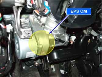
| COMPONENT LOCATION |

| GENERAL DESCRIPTION |
EPS CM controls warning lamp by sending a signal via CAN line. After sending a message, EPS CM checks signal about whether other ECU receives a signal correctly. If EPS CM receives signal from other ECU it recognizes that a message was transmitted normally.
| DTC DESCRIPTION |
EPS CM sets this code If EPS doesn′t transmit or receive a message normally.
| DTC DETECTING CONDITION |
| Item | Detecting Condition | Possible cause | ||||
| DTC Strategy |
|
| ||||
| Enable conditions |
| |||||
| Threshold value |
| |||||
| Fail Safe |
| |||||
| Restoration conditions |
|
| DIAGNOSTIC CIRCUIT DIAGRAM |

| TERMINAL AND CONNECTOR INSPECTION |
| 1. | Many malfunctions in the electrical system are caused by poor harness and terminals. Faults can also be caused by interference from other electrical systems, and mechanical or chemical damage |
| 2. | Thoroughly check all connectors (and connections) for looseness, bending, corrosion, contamination, deterioration, and/or damage. |
| 3. | Has a problem been found ?
|
| CAN SIGNAL CIRCUIT INSPECTION |
| ■ Short Check (to ground) |
| 1. | Ignition “OFF” & Engine “OFF”. |
| 2. | Disconnect the EPS CM connector. |
| 3. | Measure resistance between CAN LOW terminal, CAN HIGH terminal of the EPS CM harness connector and chassis ground.
|
| 4. | Is the measured resistance within specifications?
|
| ■ CAN BUS Resistance Check |
| 1. | Ignition “OFF” & Engine “OFF”. |
| 2. | Disconnect the EPS CM and PCM connector. |
| 3. | Measure resistance between CAN LOW terminal and CAN HIGH terminal of the EPS CM harness connector.
|
| 4. | Is the measured value within specifications?
|
| COMPONENT INSPECTION |
| 1. | Ignition “OFF”. |
| 2. | Ignition “ON” & Engine “OFF”. |
| 3. | Connect scantool and select “Diagnostic Trouble Codes(DTCs)” mode |
| 4. | Using a scantool, Clear DTC. |
| 5. | Select “Diagnostic Trouble Codes(DTCs)” mode again. |
| 6. | Are any DTCs present ?
|


