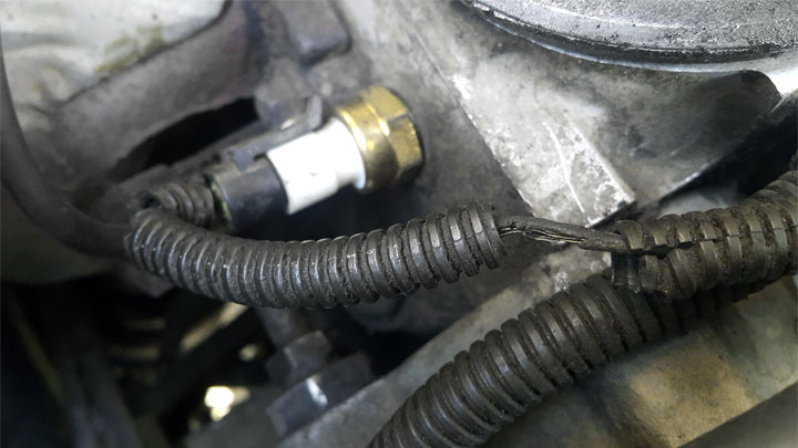
| COMPONENT LOCATION |

| GENERAL DESCRIPTION |
The Engine Coolant Temperature Sensor (ECTS) is located in the engine coolant passage of the cylinder head for detecting the engine coolant temperature. The ECTS uses a thermistor whose resistance changes with the temperature. The electrical resistance of the ECTS decreases as the temperature increases, and increases as the temperature decreases. The reference 5 V in the ECM is supplied to the ECTS via a resistor in the ECM. That is, the resistor in the ECM and the thermistor in the ECTS are connected in series. When the resistance value of the thermistor in the ECTS changes according to the engine coolant temperature, the output voltage also changes. During cold engine operation the ECM increases the fuel injection duration and controls the ignition timing using the information of engine coolant temperature to avoid engine stalling and improve drivability.
| DTC DESCRIPTION |
Checking output signals from ECTS every 80 sec. under detecting condition, if an output signal is above 4.9V for morethan 40 sec., ECM sets P0118.
| DTC DETECTING CONDITION |
| Item | Detecting Condition | Possible Cause | |||||||||||||
| DTC Strategy |
|
| |||||||||||||
| Enable Conditions | Case 1 |
| |||||||||||||
| Case 2 |
| ||||||||||||||
| Threshold value |
| ||||||||||||||
| Diagnosis Time |
| ||||||||||||||
| MIL On Condition |
| ||||||||||||||
| SPECIFICATION |
| Temp. (°C) | Resistance (kΩ) | Temp. (°C) | Resistance (kΩ) |
| -40 | 48.14 | 40 | 1.15 |
| -20 | 14.13 ~ 16.83 | 60 | 0.59 |
| 0 | 5.79 | 80 | 0.32 |
| 20 | 2.31 ~ 2.59 |
| DIAGNOSTIC CIRCUIT DIAGRAM |

| SIGNAL WAVEFORM & DATA |


Fig.1) Normal data of IATS & ECTS & EOTS at ig on
Fig.2) Normal data of IATS & ECTS & EOTS after warming up.
Fig.3) Normal waveform of ECTS
The output signals of IATS & ECTS change smoothly without any rapid changes. These 2 sensor have almost the same characteristic signal during the early period after start. It means that the temperatures of intake air and engine coolant are depended on the temperature of atmosphere. Meanwhile, During engine warm up the output signal of the ECT will change quicker than the IAT signal. even it may not change almost.
| MONITOR GDS DATA |
| 1. | Connect GDS to Data Link Connector(DLC). |
| 2. | IG “ON”. |
| 3. | Select “DTC” button, and then Press “DTC Status” to check DTC’s information from the DTCs menu. |
| 4. | Read “DTC Status” parameter.
|
| 5. | Is parameter displayed “Present fault”?
|
| TERMINAL AND CONNECTOR INSPECTION |
| 1. | Many malfunctions in the electrical system are caused by poor harness and terminals. Faults can also be caused by interference from other electrical systems, and mechanical or chemical damage. |
| 2. | Thoroughly check connectors for looseness, poor connection, bending, corrosion, contamination, deterioration, or damage. |
| 3. | Has a problem been found?
|
| SIGNAL CIRCUIT INSPECTION |
| ■ Check voltage |
| 1. | IG “OFF” and disconnect ECTS connector. |
| 2. | IG “ON” |
| 3. | Measure voltage between signal terminal of ECTS harness connector and chassis ground.
|
| 4. | Is the measured voltage within specification ?
|
| ■ Check open in harness |
| 1. | IG “OFF” and disconnect ECTS connector and ECM connector. |
| 2. | Measure resistance between signal terminal of ECTS harness connector and ECTS signal terminal of ECM harness connector.
|
| 3. | Is the measured resistance within specification ?
|
| GROUND CIRCUIT INSPECTION |
| ■ Check open in harness |
| 1. | IG “OFF” and disconnect ECTS connector and then IG “ON”. |
| 2. | Measure voltage between signal terminal of ECTS harness connector and chassis ground.(Measurement “A”) |
| 3. | Measure voltage between signal and ground terminals of ECTS harness connector.(Measurement “B”)
|
| 4. | Is the measured voltage within specification ?
|
| COMPONENT INSPECTION |
| ■ Check ECTS resistance |
| 1. | IG “OFF” and disconnect ECTS connector. |
| 2. | Measure resistance between signal and ground terminals of ECTS connector after checking out the temperature of ECTS with GDS (Component Side) Specification :
|
| 3. | Is the measured resistance within specification ?
|


