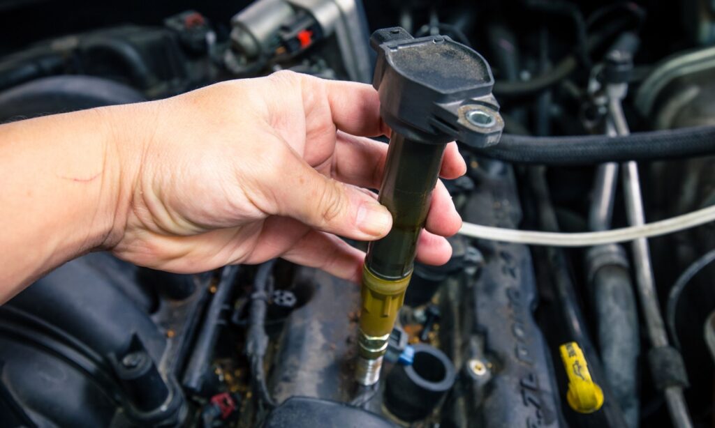
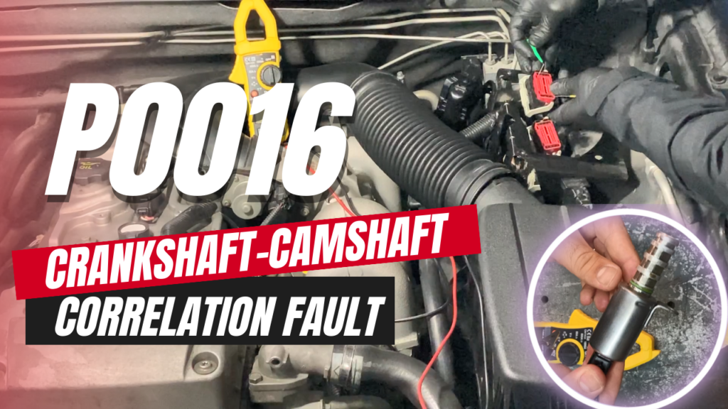
| COMPONENT LOCATION |

| GENERAL DESCRIPTION |
With the ignition switch in the ON or START position, voltage is applied to the ignition coil. Each ignition coil consists of two coils, a primary and secondary coil. The coils are mounted on top of the spark plugs. To energizing the primary ignition coils, the Engine Control Module (ECM) provides the ground for the primary circuit. The ECM uses the crankshaft position sensor and camshaft position sensor signal to time the energizing of the coil. When a primary ignition coil is energized and de-energized, the secondary coil produces a high voltage spike to the attached spark plug.
| DTC DESCRIPTION |
Checking output signals from ignition coils every 10 sec. under detecting condition, if the signals indicating open or short in the circuit are detected for more than 5 sec., ECM sets this DTC.
| DTC DETECTING CONDITION |
| Item | Detecting Condition | Possible Cause | ||||||||||
| DTC Strategy |
|
| ||||||||||
| Enable Conditions |
| |||||||||||
| Threshold value |
| |||||||||||
| Diagnosis Time |
| |||||||||||
| MIL On Condition |
|
| SPECIFICATION |
| Resistance(Ω) | Primary Coil | Secondary Coil |
| 0.62 ± 10% (20°C(68°F)) | 7.0k ± 15% (20°C(68°F))) |
| DIAGNOSTIC CIRCUIT DIAGRAM |

| SIGNAL WAVEFORM & DATA |

Fig.1) Normal waveforms of primary coil at idle.
| MONITOR GDS DATA |
| 1. | Connect GDS to Data Link Connector(DLC). |
| 2. | IG “ON”. |
| 3. | Select “DTC” button, and then Press “DTC Status” to check DTC’s information from the DTCs menu. |
| 4. | Read “DTC Status” parameter.
|
| 5. | Is parameter displayed “Present fault”?
|
| TERMINAL AND CONNECTOR INSPECTION |
| 1. | Many malfunctions in the electrical system are caused by poor harness and terminals. Faults can also be caused by interference from other electrical systems, and mechanical or chemical damage. |
| 2. | Thoroughly check connectors for looseness, poor connection, bending, corrosion, contamination, deterioration, or damage. |
| 3. | Has a problem been found?
|
| POWER CIRCUIT INSPECTION |
| ■ Check voltage |
| 1. | IG “OFF” and disconnect Ignition Coil connector. |
| 2. | IG “ON”. |
| 3. | Measure voltage between power terminal of ignition coil harness connector and chassis ground.
|
| 4. | Is the measured voltage within specification ?
|
| CONTROL CIRCUIT INSPECTION |
| ■ Check short to battery in harness |
| 1. | IG “OFF” and disconnect ignition coil connector and ECM connector. |
| 2. | Measure resistance between power and control terminals of ignition coil harness connector.
|
| 3. | Is the measured resistance within specification?
|
| ■ Check short to ground in harness |
| 1. | IG “OFF” and disconnect ignition coil connector and ECM connector. |
| 2. | Measure resistance between control terminal of ignition coil harness connector and chassis ground.
|
| 3. | Is the measured resistance within specification?
|
| ■ Check open in harness |
| 1. | IG “OFF” and disconnect Ignition Coil connector and ECM connector. |
| 2. | Measure resistance between control terminal of Ignition Coil harness connector and IG Coil #5 control terminal of ECM harness connector.
|
| 3. | Is the measured resistance within specification?
|
| COMPONENT INSPECTION |
| ■ Check Ignition Coil |
| 1. | IG “OFF” and disconnect ignition coil connector. |
| 2. | Measure resistance between power and signal terminals of ignition coil connector.(Measurement “A”) |
| 3. | Measure resistance between power terminal of ignition coil connector and out terminal of secondary ignition coil.(Measurement “B”) Specification :
|
| 4. | Is the measured resistance within specification?
|


