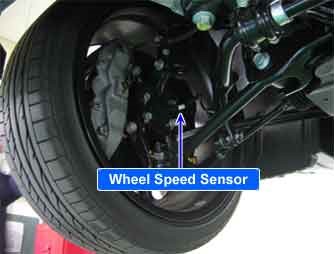
| COMPONENT LOCATION |

| GENERAL DESCRIPTION |
The wheel speed sensor is the essential component the ABS ECU uses to calculate vehicle speed and to determine whether wheel lock occurs.
For example, rear wheel speed signal is used as a reference value, for vehicle speed, in front wheel drive vehicles, and if a difference between front and rear wheel speed occurs, then ABS control is performed.
Wheel speed sensor is active hall-sensor type.
| DTC DESCRIPTION |
The ABS ECU monitors the wheel speed sensor circuit continuously.
If the sensor signal current is continuously out of the specified range for 140msec, then the HECU determines that the circuit is open/short, and sets this code.
Warning lamp is turned OFF unless additional faults are detected when the IG KEY is turned ON again, and wheel speed is more than 10 Km/h.
| DTC DETECTING CONDITION |
| Item | Detecting Condition | Possible cause | ||||||
| DTC Strategy |
|
| ||||||
| Enable Conditions |
| |||||||
| Fail Safe |
|
| SPECIFICATION |
| Sensor Type | Output Voltage | Airgap | ||
| HIGH | LOW | |||
| Active Type | 1.18~1.68V | 0.59~0.84V | 0.5~1.5mm | |
| DIAGNOSTIC CIRCUIT DIAGRAM |

| SIGNAL WAVEFORM & DATA |

Fig 1) Normal waveform of wheel speed sensor (Active type)
– High : Approx. 1.4V, Low : Approx. 0.7V
| TERMINAL AND CONNECTOR INSPECTION |
| 1. | Many malfunctions in the electrical system are caused by poor harness(es) and terminal condition. Faults can also be caused by interference from other electrical systems, and mechanical or chemical damage. |
| 2. | Thoroughly check connectors for looseness, poor connection, bending, corrosion, contamination, deterioration, or damage. |
| 3. | Has a problem been found?
|
| POWER CIRCUIT INSPECTION |
| ■ Open or Short Check |
| 1. | Ignition “ON” & Engine “OFF”. |
| 2. | Measure voltage between power terminal of the wheel speed sensor harness connector and chassis ground.
|
| 3. | Is the measured value within specifications?
|
| SIGNAL CIRCUIT INSPECTION |
| ■ Wheel speed sensor circuit check |
| 1. | Lift the vehicle. |
| 2. | Ignition “ON” & Engine “OFF”. |
| 3. | Turn the wheel by hand. |
| 4. | Measure waveform between wheel speed sensor signal terminal of the HECU harness connector and chassis ground.
|
| 5. | Is the measured waveform within specifications?
|
| COMPONENT INSPECTION |
| ■ Wheel speed sensor circuit check |
| 1. | Lift the vehicle. |
| 2. | Ignition “ON” & Engine “OFF”. |
| 3. | Turn the wheel by hand. |
| 4. | Measure waveform between signal terminal of the wheel speed sensor harness connector and chassis ground with osciloscope.
|
| 5. | Is the measured waveform within specifications?
|


Comments are closed