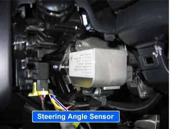
| COMPONENT LOCATION |

| GENERAL DESCRIPTION |
The Steering wheel angle sensor uses two sensors ( A-sensor and B-sensor ) to determine the direction of the rotation.
The main components of each sensor are LED, photo transistor and slit plate.
The slit plate, which has 45 holes, is installed between LED and photo transistor, and generates signals if slit plate rotates according to the steering wheel rotation.
The sensor signals are generated by photo transistor which is driven whenever the light passes through the holes. The HECU detects operating speed and direction of the steering wheel by this input signal, and the signal is used to input signal for anti-roll control.
| DTC DESCRIPTION |
The Steering Angle Sensor which is used for ESP control needs the zero-point setting for the normal operation because this sensor measures an absolute angle. The zero-point setting can be done by diagnostic tool. If the steering anlge sensor is not calibrated, the ECU detects a failure and sets this code.
| DTC DETECTING CONDITION |
| Item | Detecting Condition | Possible cause | ||||
| DTC Strategy |
|
| ||||
| Monitoring Period |
| |||||
| Enable Conditions |
| |||||
| Fail Safe |
|
| DIAGNOSTIC CIRCUIT DIAGRAM |

| MONITOR SCANTOOL DATA |
| 1. | Line up wheels like figure 1.
|
| 2. | Connect scantool to Data Link Connector(DLC). |
| 3. | Perform SAS(ASP) calibration. (figure 2) |
| 4. | Disconnect scantool from Data Link Connector(DLC). |
| 5. | Check the condition of “SAS ZERO SET” by oprerating the vehicle (turn the right and the left at least more than one time)
|
| 6. | Is “SAS ZERO SET” completed normally?
|


