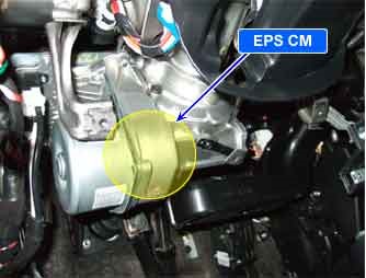
| COMPONENT LOCATION |

| GENERAL DESCRIPTION |
EPS CM receives torque and rotation speed of steering wheel from torque sensor.
The EPS CM uses a torque sensor as it’s main input for determining the amount of steering assists. The input and output shafts are separated by a torsion bar, where the torque sensor is located. The sensor consists of a two detecting plates. Detecting plate 1 is fixed to the output shaft, detecting plate 2 is fixed to the input shaft. As torque is applied to the steering column shaft the alignment of the teeth between detecting plate 1 and 2 changes. The EPS CM recognizes this change.
| DTC DESCRIPTION |
The EPS CM sets this code if torque sensor can’t calculate torque and rotation speed normally due to open or short in torque sensor circuit or discordance between 2 sensing element signal.
The EPS CM turns on warning lamp and stops assist control.
| DTC DETECTING CONDITION |
| Item | Detecting Condition | Possible cause | ||||||
| DTC Strategy |
|
| ||||||
| Enable conditions |
| |||||||
| Threshold value |
| |||||||
| Fail Safe |
| |||||||
| Restoration conditions |
|
| MONITOR SCANTOOL DATA |
| 1. | Connect scantool to Data Link Connector(DLC) |
| 2. | Ignition “ON” & Engine “ON”. |
| 3. | Turn the steering wheel to the left or right. |
| 4. | Monitor the “Torque Sensor” parameters on the Scantool.
|
| 5. | Whenever steering wheel is turned, is the steering sensor′s scantool data changed?
|
| TERMINAL AND CONNECTOR INSPECTION |
| 1. | Many malfunctions in the electrical system are caused by poor harness and terminal s. Faults can also be caused by interference from other electrical systems, and mechanical or chemical damage. |
| 2. | Thoroughly check all connectors (and connections) for looseness, bending, corrosion, contamination, deterioration, and/or damage. |
| 3. | Has a problem been found ?
|
| COMPONENT INSPECTION |
| 1. | Ignition “OFF”. |
| 2. | Ignition “ON” & Engine “OFF”. |
| 3. | Connect scantool and select “Diagnostic Trouble Codes(DTCs)” mode |
| 4. | Using a scantool, Clear DTC. |
| 5. | Operate the vehicle within DTC Detecting Condition in General Information. (turn right and left at least 1 time) |
| 6. | Select “Diagnostic Trouble Codes(DTCs)” mode again. |
| 7. | Are any DTCs present ?
|


Comments are closed