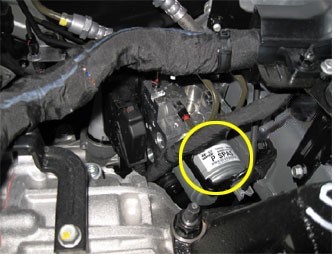
| COMPONENT LOCATION |

| GENERAL DESCRIPTION |
The HECU consists of an ECU (Electronic Control Unit ) and a HCU( Hydraulic Control Unit).
The HCU portion of the assembly contains a pump motor, solenoid valves, and accumulator.
Increase and decrease of hydraulic pressure is opreated by electronic motor, according to a measured signal by wheel speed sensor.
The function of HCU is to increase, decrease or maintain the hydralic pressure supplied to a wheel cylinder by operating return pump according to HECU control signal while ABS control is active.
The ECU monitors various sensor and switch inputs.
These inputs are used to make decisions regarding HCU component operation.
| DTC DESCRIPTION |
The HECU monitors the operation of the IC components such as memory, register, A/D converter and so on.
The ECU sets this code when the EEPROM data read by the master processor is different than prior data written, or when the master/slave processor detects abnormal operation in RAM, Status Register, Interrupt, Timer, A/D converter or cycle time.
| DTC DETECTING CONDITION |
| Item | Detecting Condition | Possible cause | ||||
| DTC Strategy |
|
| ||||
| Enable Conditions |
| |||||
| Fail Safe |
|
| DIAGNOSTIC CIRCUIT DIAGRAM |

| TERMINAL AND CONNECTOR INSPECTION |
| 1. | Many malfunctions in the electrical system are caused by poor harness(es) and terminal condition. Faults can also be caused by interference from other electrical systems, and mechanical or chemical damage. |
| 2. | Thoroughly check connectors for looseness, poor connection, bending, corrosion, contamination, deterioration, or damage. |
| 3. | Has a problem been found?
|
| COMPONENT INSPECTION |
| 1. | Ignition “OFF” & Engine “OFF”. |
| 2. | Ignition “ON” & Engine “OFF”. |
| 3. | Connect scantool and select “Diagnostic Trouble Codes(DTCs)” mode. |
| 4. | Using a scantool, Clear DTC. |
| 5. | Select “Diagnostic Trouble Codes(DTCs)” mode again. |
| 6. | Are any DTCs present ?
|


