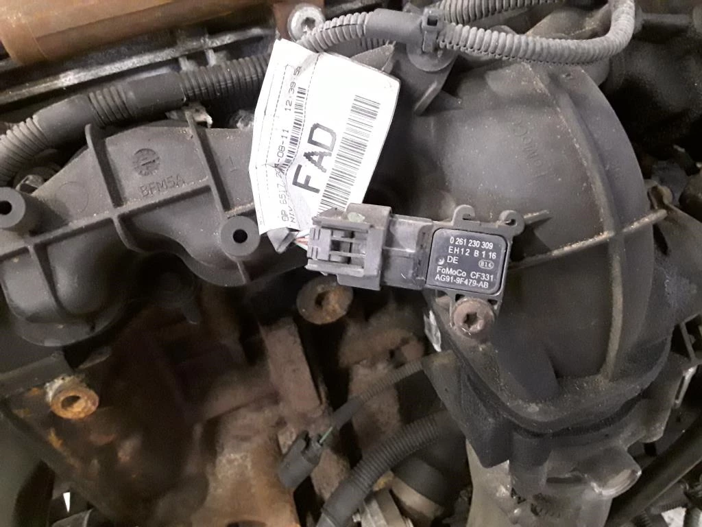
| COMPONENT LOCATION |

| GENERAL DESCRIPTION |
In order to determine the correct amount of fuel, the ECM uses the MAP to help determine the amount of intake air flow. To measure the air flow in the intake manifold, the MAFS is used at idle and MAPS is required during accelerating. The MAPS(Manifold Absolute Pressure) calculates the amount of air indirectly as measuring the pressure inside of intake manifold. This system is called a Speed-Density type.
MAPS transfers analog output signal which is proportional to the change of intake manifold pressure, then, with this signal and RPM, ECM calculates the amount of intake air flow. The MAPS is mounted on the surge tank to measure the pressure inside of intake manifold, and it consists of a piezo electric element and a hybrid IC which amplifies the output signal from the element. A diaphragm with a piezo electric element is use to convert pressure into voltage. One side of the diaphragm has a chamber with a fixed (absolute) pressure while intake pressure is applied to the other side. As the intake manifold pressure changes, the diaphram moves which changes a voltage output.
| DTC DESCRIPTION |
Checking output signals of MAPS every 5 sec. under detecting condition, if an output signal is above 4.5V for more than 2.5 sec., ECM sets P0108.
| DTC DETECTING CONDITION |
| Item | Detecting Condition | Possible Cause | |||||||||||||
| DTC Strategy |
|
| |||||||||||||
| Enable Conditions | Case 1 |
| |||||||||||||
| Case 2 |
| ||||||||||||||
| Threshold value |
| ||||||||||||||
| Diagnosis Time |
| ||||||||||||||
| MIL On Condition |
| ||||||||||||||
| SPECIFICATION |
| Pressure(kPa) | Voltage(V) |
| 20 | 0.79 |
| 46.66 | 1.84 |
| 101.32 | 4.0 |
| DIAGNOSTIC CIRCUIT DIAGRAM |

| SIGNAL WAVEFORM & DATA |


Fig.1) Normal data of MAPS at idle.
Fig.2) Normal waveform of MAPS & TPS with acceleration.
It is necessary that MAPS should be checked along with TPS. Because the MAP/TPS rationality diagnostic is comprised of two tests. A deceleration test is performed to provide a robust method for detection of an altitude compensated MAP value that is too high for the deceleration condition. The second test compares the altitude compensated MAP value to both high and low limits, dependent upon throttle position and engine speed. When the MAP value is out of the threshold range, the MAP/TPS system is determined to be failed.
| MONITOR GDS DATA |
| 1. | Connect GDS to Data Link Connector(DLC). |
| 2. | IG “ON”. |
| 3. | Select “DTC” button, and then Press “DTC Status” to check DTC’s information from the DTCs menu. |
| 4. | Read “DTC Status” parameter.
|
| 5. | Is parameter displayed “Present fault”?
|
| TERMINAL AND CONNECTOR INSPECTION |
| 1. | Many malfunctions in the electrical system are caused by poor harness and terminals. Faults can also be caused by interference from other electrical systems, and mechanical or chemical damage. |
| 2. | Thoroughly check connectors for looseness, poor connection, bending, corrosion, contamination, deterioration, or damage. |
| 3. | Has a problem been found?
|
| POWER CIRCUIT INSPECTION |
| ■ Check voltage |
| 1. | IG “OFF” and Disconnect MAPS connector. |
| 2. | IG “ON”. |
| 3. | Measure voltage between power terminal of MAPS harness connector and chassis ground.
|
| 4. | Is the measured voltage within specification ?
|
| GROUND CIRCUIT INSPECTION |
| ■ Check voltage |
| 1. | IG “OFF” and disconnect MAPS connector and then IG “ON”. |
| 2. | Measure voltage between signal terminal of MAPS harness connector and chassis ground (Measurement “A”) |
| 3. | Measure voltage between signal and ground terminals of MAPS harness connector (Measurement “B”)
|
| 4. | Is the measured voltage within specification ?
|
| SIGNAL CIRCUIT INSPECTION |
| ■ Check short to battery in harness |
| 1. | IG “OFF”. |
| 2. | Disconnect MAPS and ECM connector. |
| 3. | Measure the resistance between signal terminal of MAPS harness connector and ground.
|
| 4. | Is the measured resistance within specification ?
|
| COMPONENT INSPECTION |
| ■ Check MAPS Performance |
| 1. | IG “OFF” and install a GDS |
| 2. | Connect probe to MAPS and TPS to check signal waveform by using oscilloscope function. |
| 3. | ENG “ON” and monitor signal waveform during accelleration and decelleration.
|
| 4. | Is the relationship between the MAP and the TPS correct?
|


Comments are closed