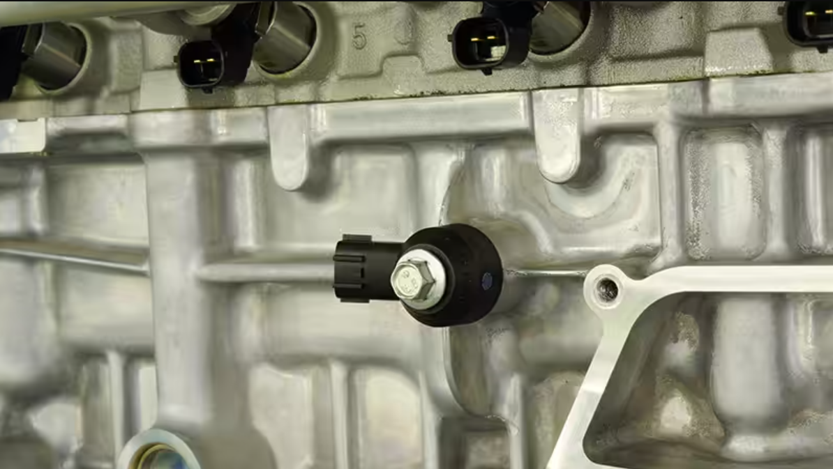
| COMPONENT LOCATION |

| GENERAL DESCRIPTION |
The knock sensor is attached to the cylinder block and senses engine knocking. The sensor contains a piezoelectric element that converts vibration (or noise) into voltage signal and sends this signal to ECM. With input signals from camshaft position and crankshaft position sensor, ECM can identify which cylinder is knocking. ECM filters vibrations and determines if the vibrations are knocking signal. The Engine Control Module (ECM) uses this signal to suppress knocking by retarding ignition timing. The ECM will set a code (Malfunction Indicator Lamp will Not turn on) if during two driving cycles the Knock sensor’s output voltage falls below minimum threshold. This code indicates an unexpected vibration is being read by the Knock sensor or ECM under normal engine operation.
| DTC DESCRIPTION |
Checking the range of input signal with a knock sensor under detecting condition, ECM senses short in knock sensor circuit or malfunction of sensor. If the average value of the knock signal is out of the threshold value during standard duration, ECM sets P0326.
| DTC DETECTING CONDITION |
| Item | Detecting Condition | Possible Cause | ||||||||||
| DTC Strategy |
|
| ||||||||||
| Enable Conditions |
| |||||||||||
| Threshold value |
| |||||||||||
| Diagnosis Time |
| |||||||||||
| MIL On Condition |
|
| DIAGNOSTIC CIRCUIT DIAGRAM |

| SIGNAL WAVEFORM & DATA |


Fig.1) Normal data of knock sensor at ig on.
Fig.2) Normal waveform of knock sensor at ig on.
| MONITOR GDS DATA |
| 1. | Connect GDS to Data Link Connector(DLC). |
| 2. | IG “ON”. |
| 3. | Select “DTC” button, and then Press “DTC Status” to check DTC’s information from the DTCs menu. |
| 4. | Read “DTC Status” parameter.
|
| 5. | Is parameter displayed “Present fault”?
|
| TERMINAL AND CONNECTOR INSPECTION |
| 1. | Many malfunctions in the electrical system are caused by poor harness and terminals. Faults can also be caused by interference from other electrical systems, and mechanical or chemical damage. |
| 2. | Thoroughly check connectors for looseness, poor connection, bending, corrosion, contamination, deterioration, or damage. |
| 3. | Has a problem been found?
|
| SIGNAL CIRCUIT INSPECTION |
| ■ Check short to battery in harness |
| 1. | IG “OFF” and disconnect knock sensor connector. |
| 2. | IG “ON”. |
| 3. | Measure voltage between low signal terminal of knock sensor harness connector and chassis ground. |
| 4. | Measure voltage between high signal terminal of knock sensor harness connector and chassis ground.
|
| 5. | Is the measured voltage within specification ?
|
| ■ Check short to ground in harness |
| 1. | IG “OFF” and disconnect knock sensor connector and ECM connector. |
| 2. | Measure resistance between low signal terminal of knock sensor harness connector and chassis ground. |
| 3. | Measure resistance between high signal terminal of knock sensor harness connector and chassis ground.
|
| 4. | Is the measured resistance within specification ?
|


Comments are closed